![]()
Optimal Buddipole (OBP) Antenna
Antenna Construction
This is the Buddipole vertical antenna made specifically for 20 meters. The antenna consists of the following parts (Buddipole part numbers shown in parenthesis).
1) Buddipole tripod mount (BPT),
2) Buddipole 16 foot mast (BML),
3) Versa-Tee interface to antenna element where guys attach (VTE) that is shown below,
4) 4 sections of 22" mast (XAA) plus the long telescopic whips (black) vertical fully extended (LTW),
5) 2 counterpoise guy wires (The Wireman, #545) cut to 17 feet (allows for length adjustments during tuning) and a 2 guys made from Dacron rope (The Wireman, #816).
The counterpoise wires are the 2 wires joined together at the midpoint of the antenna structure, joined onto the Versa-Tee black terminals. The two counterpoise elements are made from copper FLEXWEAVE #12 AWG with Black PVC jacket. The wire tensile strength is 196 lbs. The tensile strength for this Dacron rope is stated as 770 lbs so it should hold up the antenna in higher winds. The Dacron FLEXWEAVE (No. 545) and Dacron rope No. 816 can be purchased from The Wireman.
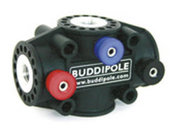
Buddipole VersaTee
Note that the wire rope is fed through the end insulator, knotted, heat shrink tubing applied and then terminated in a 3/8" diameter ring lug. The heat shrink at the end of the rope keeps the ends from fraying during repeated use.
This method removes all stress from the ring lug and keeps it on the wire rope where it belongs.
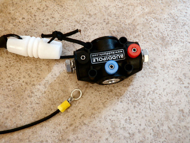
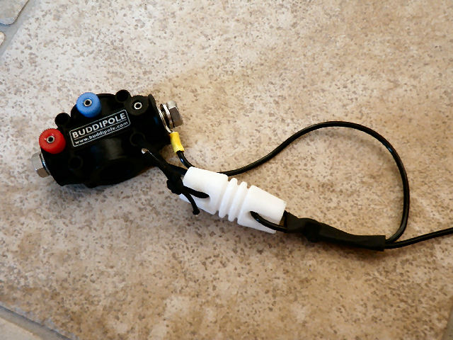
Versa-Tee with Top Insulator and Wire Rope. Bolts on each end are 3/8" dia. x 1/2" long plus lock washer, stainless steel
Raising the Antenna the EZ Way
Raising this Optimal Buddipole can be challenging the first time tried. It is not uncommon to have the antenna fall over due to wind or pulling of the counterpoise elements. Don't be the one to destroy your mast or telescopic sections due to the learning curve.
Here is my recommended method that one person can do alone. Two persons is better of course, especially the first time. Read all the steps first prior to performing them.
Step-by-Step Instructions for Antenna Raising
1. Assemble the tripod at a suitable location where the antenna is free and clear of obstructions and no power lines nearby.
2. Attach the 16 foot mast to the tripod but leave it collapsed.
3. Attach the Versa-Tee to the top of the mast.
4. Assemble the 4 Accessory Antenna Arms for a total length of 88 inches.
5. Attach the Long Telescopic Whip to the assembled antenna arms and carefully extend the whip. The overall length of this assembly is 16 feet 7 inches. The assembly is not yet attached to the mast and tripod as this will be done last.
6. Lay out the counterpoise wires with their insulators and additional Dacron lines that will be attached to guy anchor points.
7. Attach each counterpoise or guy line to the Versa-Tee. I use a little Dacron line threaded through the 4 holes in the Versa-Tee.
8. With the guy lines/counterpoise wires attached to the Versa-Tee, keep these at right angles to each other and lay them outward from the mast towards their estimated guy anchor points.
9. Next, raise each mast section to fully extend the mast to it maximum height. Note the telescopic whip is still not attached yet.
10. Now proceed to opposite guy lines/counterpoise wires and secure each to the anchor point. The anchor point could be a stake, tree limb, or fence post. Do not tighten too much on your first pass of this step. Proceed around to all 4 anchor points a second time and make each line a little tighter. Once completed, the tripod and mast should be firm. If you need to, you can move the complete tripod and mast to find the exact center point with equal tension on all guy lines.
11. Now lower the mast assembly to its nested position being careful not to move the tripod's location.
12. Attach the coax cable with balun to the Versa-Tee using the miniature banana plugs. Use the strap that is wrapped around the balun to secure it to the mast just below the Versa-Tee.
13. Take the Accessory Antenna Arms with Whip fully extended and screw onto the nested mast. If it is windy, you may want a helper to keep the tripod steady.
14. Next, fully extend the mast assembly until there is tension in the guy lines/counterpoise wires.
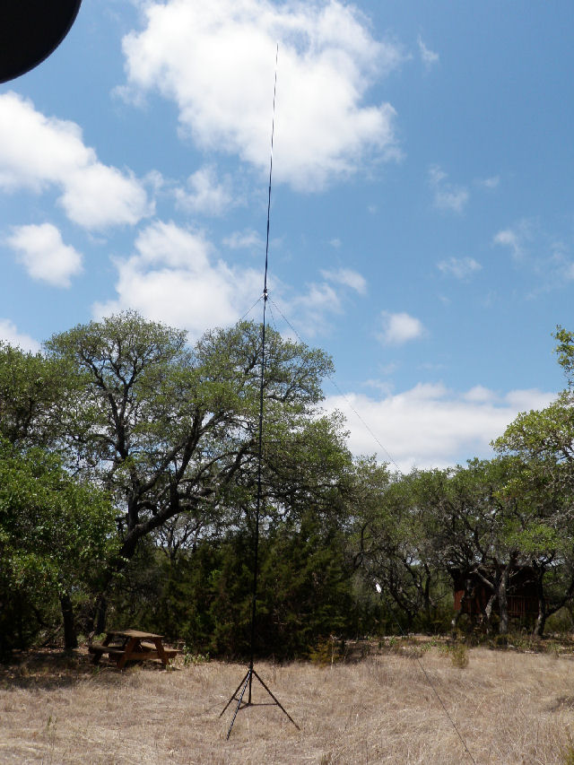
15. If necessary, you can again move the tripod so the mast and antenna is centered and vertical. Below shows the fully erect mast with antenna at the top with tension in all the guy/counterpoise wires.
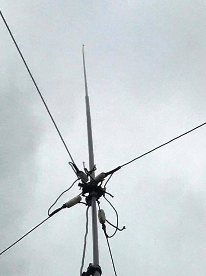
Completed Antenna View Looking Straight Up From Tripod
Alternate Configurations
One interesting variant is to use an alternate feed line and connect the black and red terminals so the counterpoise actually becomes an inverted-vee antenna. By switching feed lines between the vertical element (blue terminal on Versa-Tee) and the red terminals, an effective Vertically / Horizontally polarized antenna can be created. This should allow for optimization between DX / NVIS operations, respectively.
Double feed lines can be brought down the mast or a small relay can be used to select between the two antenna - your choice. A bias-T can used in the shack and at the antenna to inject and extract the 12 VDC power to provide relay operation.
A feed line length of an electrical quarter wave can also be chosen and the coax end left unterminated (which is an open circuit). The open circuit translates to an electrical short at the red and black terminals. If this technique is selected, the relay must disconnect both center conductor and shield of the inverted-vee feed line. I hope to gather some S-meter data between these two configurations to demonstrate if this is an effective choice for the ham radio operator.
Another configuration is to use 4 guy wires to support the mast, two that are the counterpoise for 20 meters and another two that are cut to 40 meters (about 31 feet for each leg). Each leg of the 40 meter guy wire should be connected to a leg of the 20 meter guy wire. The 20/40 meter dipoles are essentially in parallel and operate independently since the bands are a factor of 2. This means at 40 meter, the 20 meter antenna has minimal affect to 40 meter operation. At 20 meter, the 40 meter dipole appears as a very high impedance and also provides minimal affect to 20 meter operation.
Above is the alternate configuration for a dual feedline approach (Click to Download a PDF file)
The tri-band feature uses the 40 meter dipole at its 3rd harmonic to achieve operation on 15 meters. Thus the overall antenna will provide 40/15 meters and 20 meters on one mast. Pretty neat idea for portable operations.
Since no switching is needed between the 40 and 20 meter dipole guy wires, the 20 meter vertical section can still be employed when the tri-band operation is wanted. This will allow optimal polarization selection for the 20 meter band.
Completed Optimal Buddipole Used During Field Day
Antenna Tuning
Due to the number of variances in location where the antenna is installed, the lengths of the wire may need to be adjusted slightly from dimensions given. Antenna tuning is accomplished by folding back the counterpoise end points so the overall length is varied. Folding back the elements allows for the overall length to be adjusted shorter or longer as needed during the tuning process. I like to use zip ties to keep the ends in place but allows for cutting and removing to make small length adjustments in the future.
The ends of the wires feed through an antenna insulator appearing white in the photo above. Once folded back, UV resistant tie-wraps are used to secure the wire to itself keeping the chosen length constant. By symmetrically adjusting both counterpoise elements at the same time and then taking a VSWR measurement, the antenna resonance can be optimized for the 20 meter band. I had no problem getting the antenna to resonant over the entire band that was an easy impedance match for my transceiver.
Here is some advice on how to tune the basic 20 meter antenna.
Counterpoise Tuning
1. It is important when tuning to find the point of lowest SWR even if it is out-of-band. That way you can use that information to adjust the length of the counterpoises by the same percentage the low point is from your desired, final tuned location.
As an example, if the lowest SWR is found to be 13.7 MHz and you want moved to 14.2 MHz, that is low by 3.6%. So to move the resonant frequency higher, you have to shorten the counterpoise elements by 3.6%. Do this by folding back the ends of the counterpoise by that amount and re-measure. It might take one more trial to fine tune to the frequency of interest.
2. If the antenna's vertical element is too close to trees, it will affect the tuning of the antenna. It is important to be in the clear about a half wavelength (about 30 feet) if possible. Especially keep the upper portion of the antenna away from objects for that is where the electric field is greatest.
3. For best pattern performance for pattern symmetry, try to have the 2 counterpoise elements at opposite sides of the antenna. Otherwise there will be pattern distortion.
4. Another method is to tune the 2 counterpoise elements as a dipole antenna. That way you can find resonance via the lowest SWR. Then connect the two wires together again as the counterpoise and attach the vertical element to the center of the coax cable.
5. The antenna will tune somewhere near where you want to operate. You will just need to find the initial resonance and move it to where you want it. Murphy's Law states it will always initially be out-of-band.
VSWR Plots for the Completed Antenna
An AIM4170D RF network analyzer running AIM 910B software was used to measure the impedance of the antenna in several configurations.
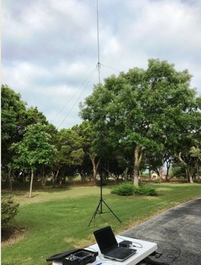
Field Test Setup for Making Impedance Measurements
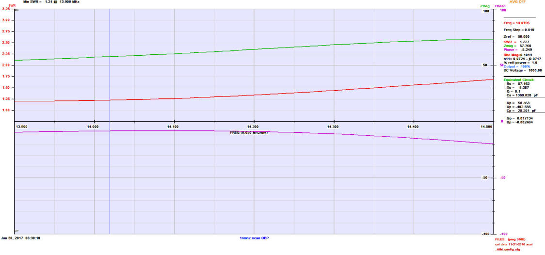
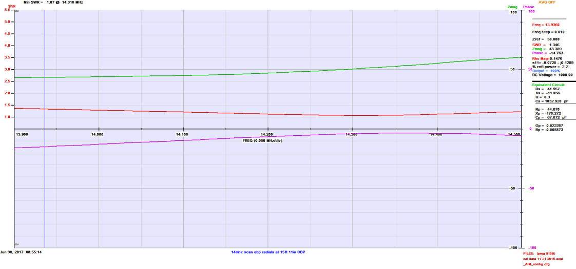
A. Configuration, Vertical with 2 Counterpoise Elements
Vertical Section Length: 16' 7"
Counterpoise (2) Length: 16' 10"
Min. VSWR at 13.9 MHz. (Maximum Scale for VSWR is 3.25, Red is VSWR, Purple is Phase)
Based on the lowest VSWR outside of the 20m band, the length of the counterpoise was reduced slightly and the measurement run again.
B. Configuration, Vertical with 2 Counterpoise Elements (Lengths Slightly Shorter)
Vertical Section Length: 16' 7"
Counterpoise (2) Length: 15' 11"
Min. VSWR at 14.3 MHz. (Maximum Scale for VSWR is 5.5, Red is VSWR, Purple is Phase)
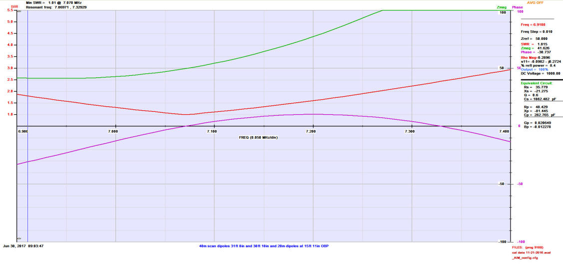
C. Configuration, Cross Inverted Vee Dipole for 40/15m and 20m
Vertical Section Length: 16' 7"
20m Dipole Length: 15' 11"
40m Dipole Length: 31' 0"
This is the 40m plot. (Maximum Scale for VSWR is 5.5, Red is VSWR, Purple is Phase)
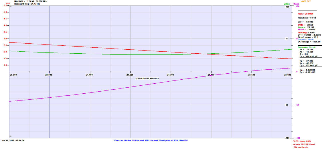
Next is the 40m dipole but scanned at 15m. (Maximum Scale for VSWR is 5.5, Red is VSWR, Purple is Phase)
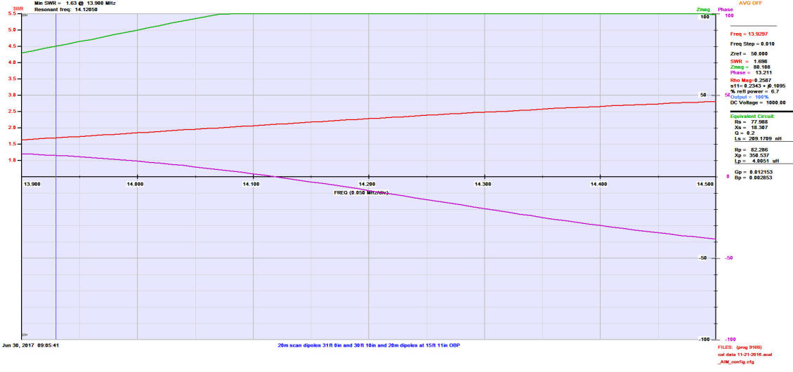
Finally, this is the 20m dipole response. (Maximum Scale for VSWR is 5.5, Red is VSWR, Purple is Phase)
Antenna Storage
One thing about wire antennas is the fact that they can be easy to store. The Optimal Buddipole can be rolled up onto a cable spool that is found at your local Lowe's or Home Depot. It is commonly used to roll up power extension cords. Just roll it up and put it away until it is needed on another day.
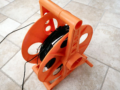
Roll-Up Antenna Spool
Download these Documents
Download the Optimal Buddipole document now: The Optimal Buddipole (OBP) (PDF)
Download the Optimal Buddipole Alternate Configuration Drawing now:
1) The Optimal Buddipole Alternate Configuration (PDF) and
2) OBP Relay Module Wiring (PDF)
-Copyright © 2001-2017 K5PA Home Page
e-mail to: k5pa@arrl.net