Portable Radio Ops Using Batteries
With the Sun as an Energy Source!
K5PA Discusses Using the Excel Spread Sheet Model BattOpTime.xls
One of the neat aspects of ham radio operations is going out into the field and operating using different energy sources. I have been interested in battery operations from the field using QRP (5 W or less) RF output power. At these power levels, a small battery, such as 7 Amp-Hours, can supply enough energy to make many, many contacts in the field. What happens if you want to work longer than the energy source allows? Well, this is where alternate energy sources can be applied.
Photo Voltaic, or PV for short, are solar cells normally mounted in an array to develop enough voltage and current to add charge into a battery power source. The larger the PV array, the higher the charging capability.
There are trade-offs between cost of energy from different sources. Question, is it cheaper to add additional batteries or to use larger solar cell arrays?
Another problem arises when additional RF output power is desirable to establish communications. In other words, when QRP ops is just not enough, how much more battery power and/or PV arrays are needed to offset the increase in RF power?
I have performed an analysis of what parameters need to be assessed to make decisions on battery capacity (in Amp-Hours), solar cell array sizing, RF power output, and many more factors. What started out to be a simple Excel sheet to perform these calculations (like back of the envelope estimates) turned into a pretty nice spread sheet to help manage all the factors. The filename is ' BattOpTime.xls .' A link is given below for downloading from this web site. (Please read and agree to the license agreement below and included in the spread sheet prior to use of this model)
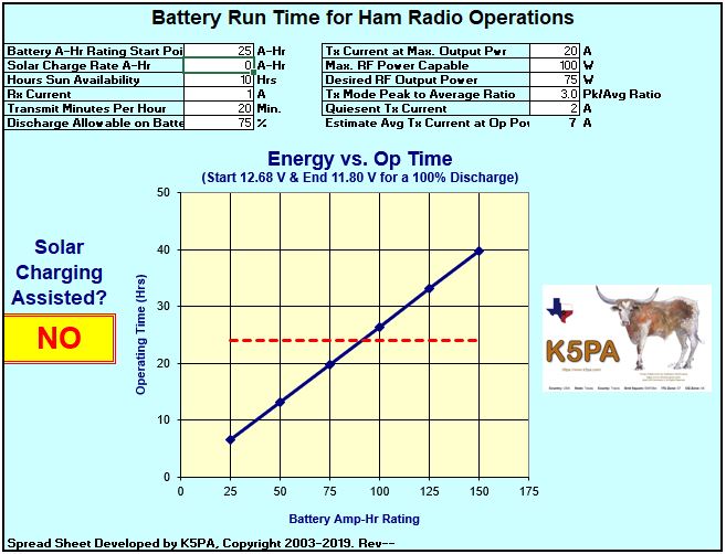
In the screen capture below, I show the panel that is used for data entry and the resulting calculations. I used a horizontal dotted red-line to indicate a 24 hour operating period. Other time periods can also be used just by using the vertical axis to find you operating time. Based on all the parameters in the spread sheet, a graph is produced giving operating time versus battery capacity (Amp-Hours).
To download Excel spreadsheet,
click here
![]() BattOpTime.xls
(approximately 43 kB).
BattOpTime.xls
(approximately 43 kB).
With your mouse, right click for Windows to 'Save Target As' to disk. Left click if you want to load and run the program from your browser.
Definitions of Entries (manually enter data only in white cells please)
Battery A-Hr Rating Start Point. The graph above has an x-axis that starts at a certain A-Hr battery rating. Input the starting point for your battery in this cell. For example, if you have a 7 A-Hr battery then you would enter anything less than or equal to 7 in order for the graph to include your battery's capacity. The graph is then incremented automatically in 25 A-Hr steps.
Solar Charge Rate A-Hr. If you are using a solar cell array to charge your battery, then enter the maximum number of Amps that is available for your array. If you do not have a solar battery charging capability, enter zero (0). The value of zero will change the text in the bright yellow square to indicate if solar power is used or not used.
Hours of Sun Availability. The amount of energy available from a solar array depends on the amount of daylight. Put in your estimate here. For example, if you expect full sunlight from 8 AM to 6 PM, then enter 10 hours. You can also estimate that if your skies are partly cloudy, then a proportionally lower number of sunlight hours are available. The current model is pretty simple in this area. It is an area that will be enhanced if enough interest if given.
Rx Current. Radios require a certain amount of DC current during operations. You can measure you nominal receive current or take it from your equipment's specifications listed in the manual. Note that at high audio output, the receiver current increases. If you use a fairly medium to low volume, then the current is less. In this model, the receiver current is expected to be continuous during radio operation.
Transmit Minutes Per Hour. The amount of transmit time in a one hour period is entered in this cell. If the radio is not transmitting, it is assumed to be receiving. Thus, this transmit time is used to calculate transmit duty cycle. During contests, the duty cycle is likely higher than during regular tuning, listening, and transmitting times. An entry of 20 minutes per hour is calculated as a transmit duty cycle of 33.3% (20 minutes divided by 60 minutes). For digital modes, the transmit times are a fraction of the total time listening. For example, FT8 has a transmit time of 12.64 seconds for every 30 seconds of a Tx+Rx cycle (12.64/30 = 42% Tx time over an hour is 25.2 minutes) whereas FT4 has a 5.04 seconds transmitting over a 15 second cycle (5.04/15 = 34% over an hour is 20.4 minutes). So these would be the upper extremes transmit minutes per hour for FT8 and FT4 modes..
Discharge Allowable on Battery. Batteries have a certain capacity rated in A-Hrs. For example, a 100 A-Hr (at 100% capacity) battery will completely discharge to 0% capacity in 5 hours if 20 Amps per hour is being drawn from the battery (simply 5 hrs times 20 A = 100 A-Hrs).
Lead acid, 12 VDC batteries have an open circuit voltage equal to the following: 100% capacity > 12.68 Volts; 75% capacity = 12.44 volts; 50% capacity = 12.23 volts; 25% capacity = 12.02 volts; and 0% capacity equals 11.8 volts. To lengthen the number of charge cycles for a battery, the discharge should be kept to around 50%. You can increase this, say to 75% as long as it is on an irregular basis. Otherwise, the battery's useful life time will suffer.
Gel Electrolyte, 12 VDC batteries have a different open circuit voltage from lead acid. Their voltage and capacity are: 100% capacity > 12.95 Volts; 75% capacity = 12.71 volts; 50% capacity = 12.50 volts; 25% capacity = 12.29 volts; and 0% capacity equals 12.07 volts.
Tx Current at Max. Output Power. The transmitter has a maximum current rating when the maximum output RF power is generated. The radio's specification sheet (see manual) normally gives this number. Typically, a 100W RF output transmitter requires about 20 A of DC current.
Max. RF Power Capable. Enter the maximum RF power capability for the radio that coincides with the maximum DC amperage above.
Desired RF Output Power. Most radio provide a means to decrease the RF output power. This is useful for decreasing DC current requirements which then lengthens the time a battery can be used. This model assumes a linear relationship between maximum RF output power at maximum DC current with a lower bounds at the transmitter's quiescent current (transmit mode stand by current when no modulation is present). The value of the quiescent current is entered as listed below.
Tx Mode Peak-to-Average Ratio. Different modes of operation have different peak power to average power ratings. This is important since operating with voice SSB requires a different average DC current than a digital mode such as PSK31. A good assumption with SSB operations without speech compression, the peak to average is about 3:1, entered as 3. For Morse code, CW operations, the peak to average can be entered as 2. For PSK31, enter a value of 1. These are not rigorous values and certainly open to interpretation. If speech compression is being used, the peak to average ratio is increased. I suggest a value of 1.3.
Quiescent Tx Current. This is the nominal current the transmitter draws from the battery when no modulation is applied. This becomes the lower bounds for the transmit current consumption. The value may be found in the radio's specification sheet in the manual. The quiescent current is likely higher than the receiver current.
The figure below shows the effect of using a solar cell array charging of the battery. In this example, the solar cell array is listed as having 2.33 A-Hr of capacity. This means that in a one hour time period, the solar cell array will provide 2.33 Amps into the battery. The solar cells operating amperage can be found in the specification sheet. Notice the bright yellow cell indicates the system is being charged from the solar cell source.
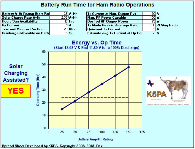
To interpret this graph, remember the dotted red-line is 24 hours. So to operate under the conditions given in the white data entry cells, you can operate for about 24 hours if you are using a 65 A-Hr battery capacity. Compare this to the first graph above. With no solar cell array battery charging, the same conditions requires a battery capacity of 89 A-Hrs.
So to address an earlier question, is it cheaper to add the solar assisted battery charging or just purchase a larger battery? These types of trade-offs can be found by using this model One important concept to remember however is that, at some point, all batteries require charging So you have to have a charging source from somewhere. Why not solar?
![]()
BattOpTime.xls Excel Spread Sheet License Agreement
1) This MS Excel spread sheet software comes without warranty of any kind. The user agrees to bear all risk associated with using the spread sheet software. The author shall not be liable for damages of any kind which result from use of this software in any manner.
2) This Excel spread sheet software may be freely distributed, but only in its original form (that is, only as the file BattOpTime.xls, as originally published and unmodified). No fee (other than a nominal fee for the cost of media) may be charged for this software. This software may not be distributed as part of a package of commercial hardware and/or software (for which an other-than-nominal fee is charged) without first obtaining permission from the author.
If you do not agree with these terms and conditions, you are not authorized to use this software and must delete it from your computer.
Please contact the author with any questions or comments regarding this software:
Gene Hinkle, K5PA
e-mail: k5pa@arrl.net
To read instructions on the use of the spreadsheet and to download the latest copy, visit the author's website at
This Excel spread sheet software is protected by the copyright laws of the United States of America, F. E. Hinkle K5PA Copyright 2003-2019