Mobile Operations
Here are the latest photos of my HF/V/UHF mobile radio station mounted in my 2006 Toyota Highlander. I am using an ICOM IC-7000 portable/mobile radio that provides coverage for all these bands. The IC-7000 has seperate HF and V/UHF antenna connections so it only requires to coaxial cable to connect to the antennas. Plus, the IC-7000 has the removable control head that makes it very simple to mount near the dash and keep the main body in the rear cabin area.
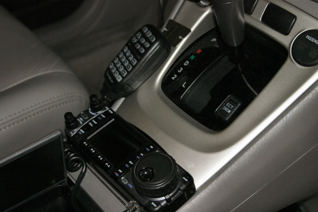
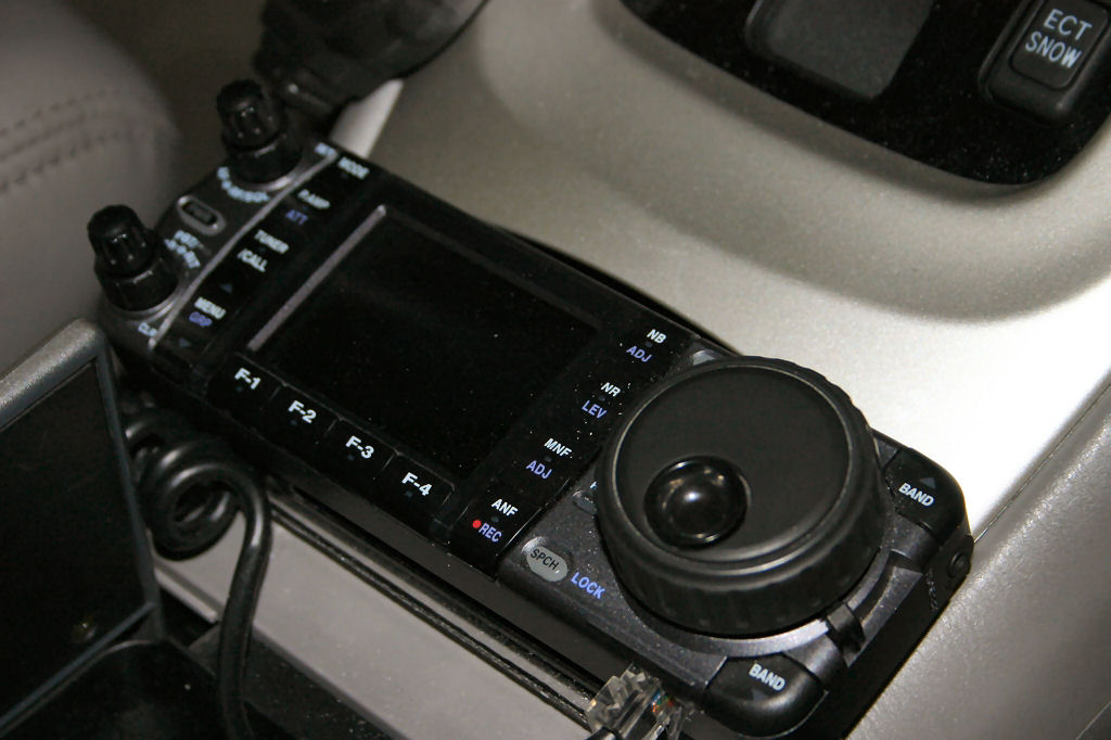
ICOM IC-7000 control head mounting on the center console. A surface, double sided tape mounted microphone clip is just above the control head. Here is a closer look of the image.
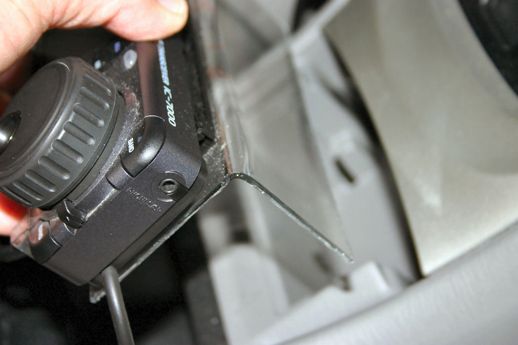
I used a small piece of Lexan plastic material from Home Depot, softened it with an electric heater gun to form an angle bend and slipped it into the ash tray slot. Very nice an easy. The ashtray is removed but stored under the console in case it is every needed.
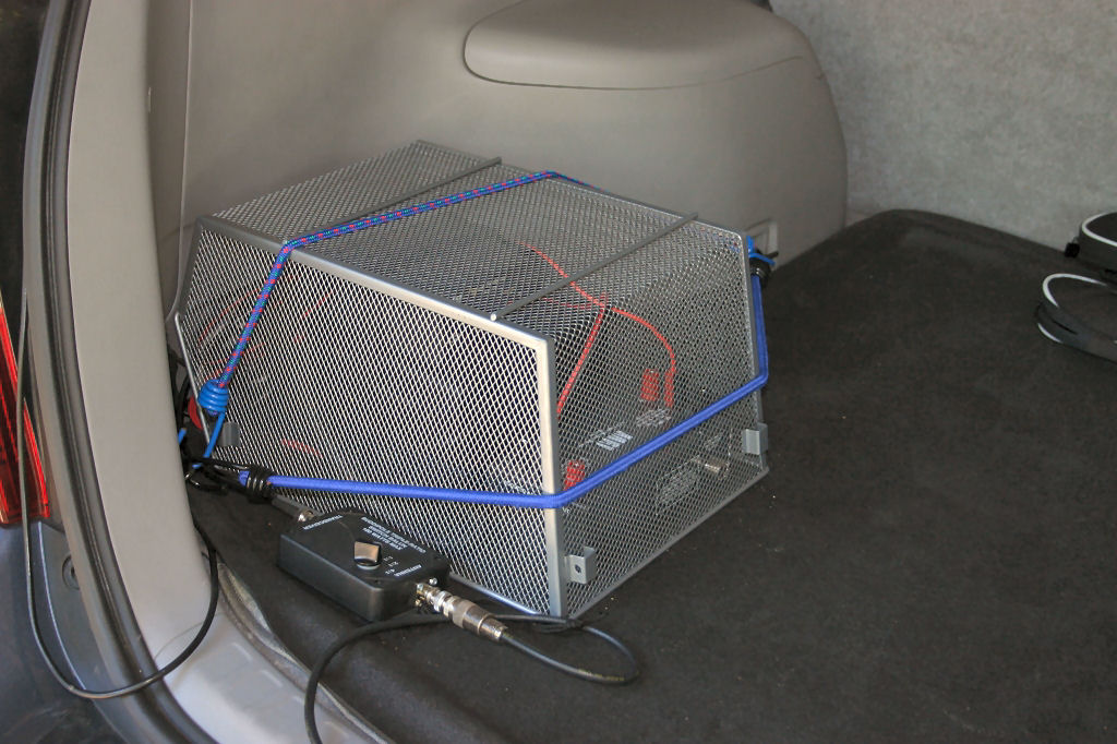
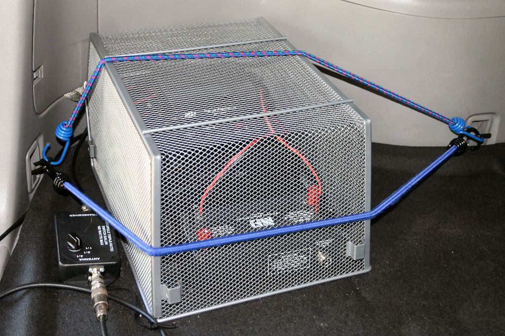
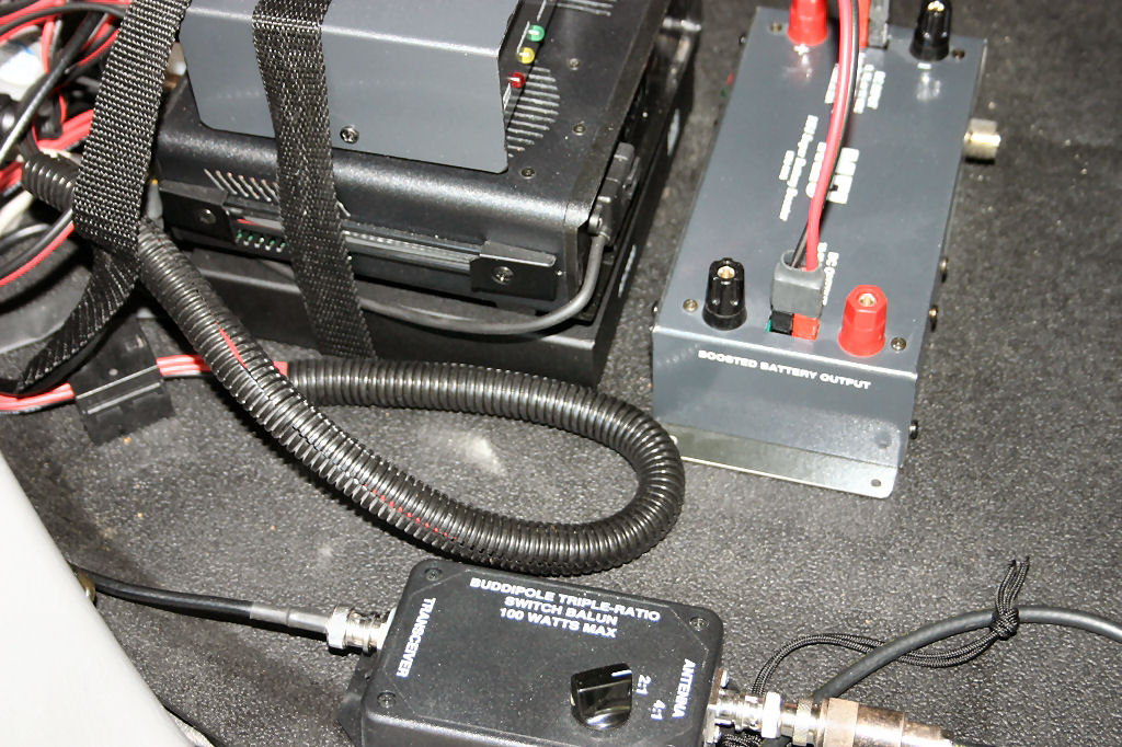
Here is the cage (Note: See the 2011 Update Below) that keeps the mobile equipment from bouncing around the cabin. It has a metal frame and wire mesh that is being restrained with bungee cords. To the left you can see an RF transformer called the Triple Ratio Switch Balun (TRSB). This connects the IC-7000 to the HF antenna system. I use the Hustler brand of antenna coils. On 20 meters and above I select the 50 ohm (1:1) impedance selection. For 40 meters, I select the 4:1 setting. The TRSB transformer is available from the Buddipole website ( http://www.buddipole.com/trraswbat.html ) and is rated at 100 Watts.
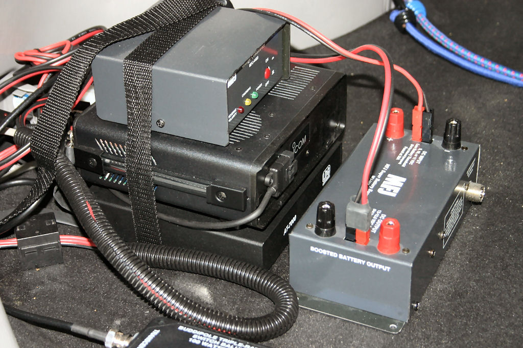
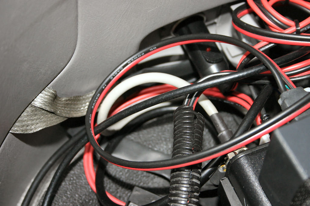
Here is what is inside the cage.
DC POWER: The car's 12 VDC power first connects to an MFJ-4403 Voltage Conditioner and then to the MFG-4416 Battery Booster ( http://www.mfjenterprises.com/ ). The voltage that is presented to the IC-7000 is extremely well conditioned and is set to 13.8 VDC regardless whether the engine is running or not.
UPDATED 2011:
Download Power Interconnect Now (pdf file): Interconnect
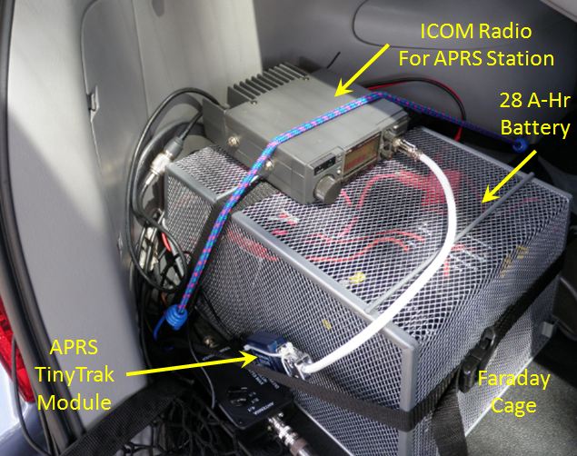
In 2011, I updated the design as shown in the schematic below. A new photo of the cage is shown below.
(On top of the cage I also mounted my 2 meter APRS transceiver with TinyTrak module. A GPS antenna is roof mounted.)
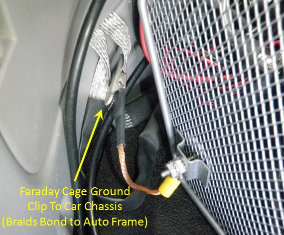
The cage is also grounded to the car chassis as shown in the photo below.
Parts List
| Description | Vendor | Part Number | Web Site |
| Automatic Power Off Switch | West Mountain Radio | APO3 | http://www.westmountainradio.com/ |
| Power Gate | West Mountain Radio | PG40 | http://www.westmountainradio.com/ |
| Power Relay | Power werx.com | SPDT40M | http://www.powerwerx.com/ |
| Battery, 12 Volt 35Ah AGM, Werker Battery 12V Werker Sealed Lead Acid Battery | Batteries Plus | WKA12-35C | http://www.batteriesplus.com |
| Power Booster | MFJ | MFJ-4410 | http://www.mfjenterprises.com/index.php |
| Cigar Lighter to Power Pole Adapter | Power werx.com | C2P-5 | http://www.powerwerx.com/ |
ICOM IC-7000: The radio is connected to the remote head via the factory extension cable. The radio's audio output using is also run to the front console (using a 1/8" phone plug extension cable) where there is a small speaker. The RF output connects to an RF tuner directly below the ICOM unit.
RF POWER: The RF power connects to the LDG AT-7000 ( http://www.ldgelectronics.com/ ) automatic tuner that works extremely well. It is now discontinued but the newer line of automatic tuners would work just as well (if not better due to the inclusion of frequency measurement circuitry).
GROUNDING: It is very important to provide a low impedance, direct bond of the ICOM IC-7000 radio and AT-7000 antenna tuner to the car chassis. In the photograph you can see the silver colored, wire braid that is used to directly connect the radio and tuner ground studs to under the plastic service panel where I made a solid metal connection to the car's frame.
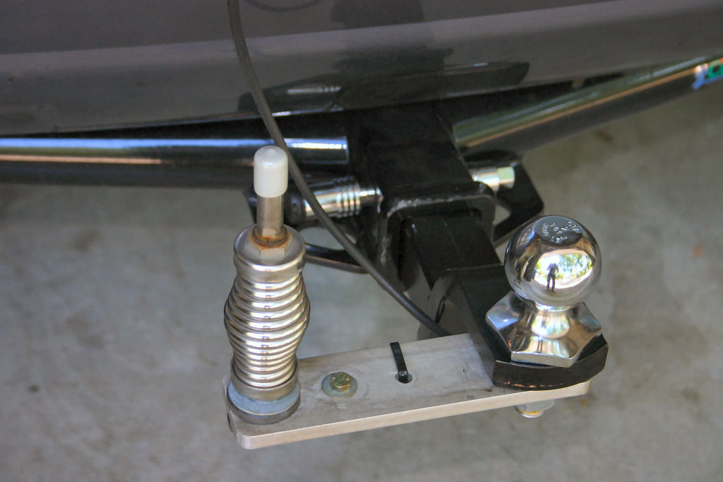
HITCH MOUNT: Here is the antenna mount for the Hustler mast and coil. It consists of a quick disconnect above the spring (with a plastic cover for protection when the antenna is not mounted). The antenna mount is an aluminum plate that is secured with the 2 inch ball nut. The tie wrap secures the RF cable to the bracket.
Now here is an important addition. The hitch (2") coupler is secured in place by a vibration resistant locking pin. The pin has a nut that is tightened so it cannot vibrate during movement. Otherwise, the hitch mount would rattle going over the roadway and become very annoying. It may also help ground the mount but this should not be used as the main RF ground connection to the frame. Instead, a braided copper wire is being used (not shown at the time the photo was taken) to provide a better RF connection to the car frame. The hitch pin can be purchased at a local auto parts store.